
The following audio examples accompany the submission (manuscript and code)
H. Helmholz, T. Deppisch, and J. Ahrens, “End-to-End Magnitude Least Squares Binaural Rendering for Equatorial Microphone Arrays,” in Fortschritte der Akustik — DAGA 2023, 2023, pp. 1679–1682.
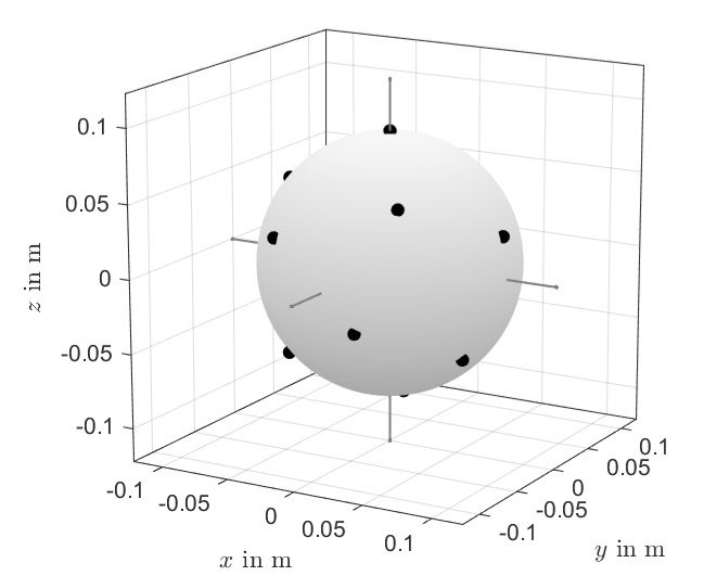
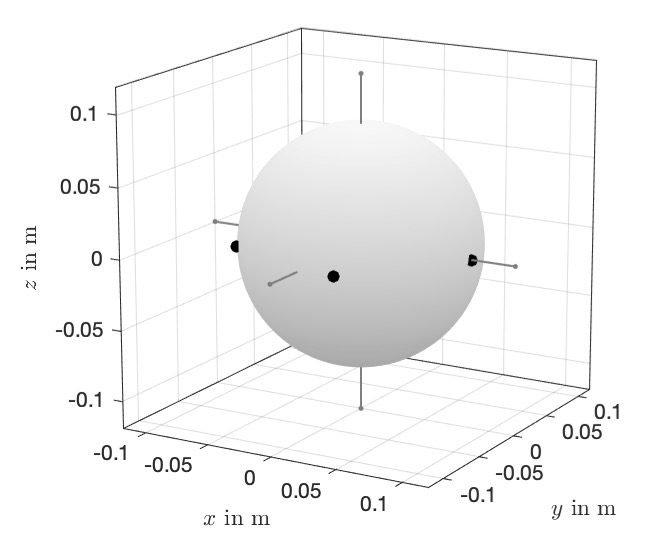
The given binaural renderings provide auralizations for the microphone array configurations and acoustic scenarios used in the manuscript. This comprises array configurations at 2nd spherical harmonics order (SH2) from a spherical microphone array (SMA) and an equatorial microphone array (EMA). The microphone arrangements are shown in the following (equivalent to Figure 1 in the manuscript).
| SMA (SH2) (14 microphones, t-design) |
EMA (SH2) (5 microphones, equiangular) |
 |
 |
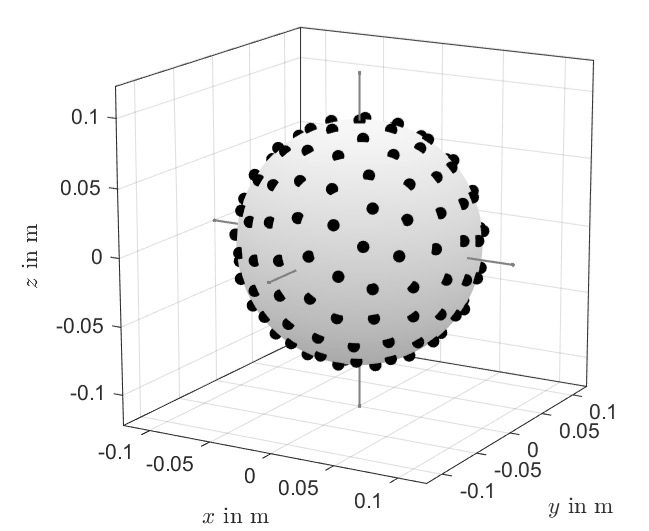
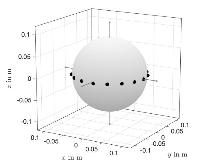
We also include binaural rendering examples with auralizations and plots for microphone arrays at 8th spherical harmonics order (SH8). The microphone arrangements are shown in the following (it was impossible to include these examples in the manuscript due to space constraints).
| SMA (SH8) (146 microphones, t-design) |
EMA (SH8) (17 microphones, equiangular) |
 |
 |
All listening examples are precomputed for two static head orientations, 0° (frontal) and 90° (lateral or above), as well as a continuous horizontal/vertical head rotation (0° – 360°). The binaural rendering involves the Neumann KU100 dummy head from the TH Cologne dataset.
The given audio examples may sound very quiet. In this case, increase (or maximize) the output level of your headphones. This is necessary to prevent clipping in the rendered audio signals while preserving the full dynamic range of the measurement data.
Examples of Horizontal Head Rotations
Anechoic environment
The following examples auralize an anechoic environment based on a simulated plane wave impinging from the frontal direction on the microphone arrays.
The plots in the first column are identical to Figure 3 (top) in the manuscript, i.e., showing the resulting median and 5th to 95th percentile deviations over a full horizontal head rotation. The plots in the second column compare the differences between the reference and the respective array renderings with and without eMagLS in more detail (not included in the manuscript).
| Anechoic environment |
Frontal (0°) |
Lateral (90°) |
Rotation (0° – 360°) |
|
| Reference | ||||
| SMA (SH2) plot |
raw plot |
|||
| eMagLS plot |
||||
| EMA (SH2) plot |
raw plot |
|||
| eMagLS plot |
||||
| SMA (SH8) plot |
raw plot |
|||
| eMagLS plot |
||||
| EMA (SH8) plot |
raw plot |
|||
| eMagLS plot |
Comment: The simulated SMAs and EMAs in the manuscript (and above) exhibit an array radius of 8.5 cm. The median errors due to spatial aliasing and SH order truncation are of similar magnitude and, thereby, do not cause an overall attenuation of high frequencies even at very low SH orders. Therefore, the benefit of eMagLS in correcting the overall timbre of the renderings is relatively small for microphone arrays of this size. eMagLS still yields clear improvements in the direction-dependent spectral magnitude of the array renderings.
The following table contains auralizations and plots of the popular Eigenmike EM32 (SMA, 32 microphones) array rendered at 4th spherical harmonics order (SH4). According to the smaller array radius of 4.2 cm, the benefits from eMagLS rendering are much more substantial due to the compensation of the attenuation at high frequencies.
| Anechoic environment |
Frontal (0°) |
Lateral (90°) |
Rotation (0° – 360°) |
|
| Reference | ||||
| EM32 (SH4) plot |
raw plot |
|||
| eMagLS plot |
||||
Room environment
The following examples auralize a large and reverberant room environment based on the “Large Broadcasting Studio” (LBS) from the dataset of the WDR Broadcast Studios.
The plots in the first column are identical to Figure 3 (bottom) in the manuscript, i.e., showing the resulting median and 5th to 95th percentile deviations over a full horizontal head rotation. The plots in the second column compare the differences between the reference and the respective array renderings with and without eMagLS in more detail (not included in the manuscript).
| Room environment |
Frontal (0°) |
Lateral (90°) |
Rotation (0° – 360°) |
|
| Reference | ||||
| SMA (SH2) plot |
raw plot |
|||
| eMagLS plot |
||||
| EMA (SH2) plot |
raw plot |
|||
| eMagLS plot |
||||
| SMA (SH8) plot |
raw plot |
|||
| eMagLS plot |
||||
| EMA (SH8) plot |
raw plot |
|||
| eMagLS plot |
Examples of Vertical Head Rotations
Anechoic environment
The following examples auralize the same anechoic environment based on a simulated plane wave impinging from the frontal direction on the microphone arrays.
The plots in the first column are identical to Figure 4 (top) in the manuscript, i.e., showing the resulting median and 5th to 95th percentile deviations over a full vertical head rotation. The plots in the second column compare the differences between the reference and the respective array renderings with and without eMagLS in more detail (not included in the manuscript).
| Anechoic environment |
Frontal (0°) |
Above (90°) |
Rotation (0° – 360°) |
|
| Reference | ||||
| SMA (SH2) plot |
raw plot |
|||
| eMagLS plot |
||||
| EMA (SH2) plot |
raw plot |
|||
| eMagLS plot |
||||
| SMA (SH8) plot |
raw plot |
|||
| eMagLS plot |
||||
| EMA (SH8) plot |
raw plot |
|||
| eMagLS plot |
The following table contains auralizations and plots of the same Eigenmike EM32 (SMA, 32 microphones) array rendered at 4th spherical harmonics order (SH4). According to the smaller array radius of 4.2 cm, the benefits from eMagLS rendering are much more substantial due to the compensation of the attenuation at high frequencies.
Comment: The perception of source elevation from non-individualized HRTFs in an anechoic environment is a highly individual effect. We hear that the given example of the statically rendered HRTF reference below invokes some perception of source elevation in the listener. However, the “raw” rendering of the Eigenmike EM32 cannot convey these monaural elevation cues. The eMagLS rendering, on the other hand, can restore some of the otherwise missing perceived source elevation. Therefore, eMagLS may be capable of improving elevation perception in the case of microphone arrays where relevant direction-dependent cues can be restored by the equalization method.
| Anechoic environment |
Frontal (0°) |
Above (90°) |
Rotation (0° – 360°) |
|
| Reference | ||||
| EM32 (SH4) plot |
raw plot |
|||
| eMagLS plot |
||||
Room environment
The following examples auralize the same large and reverberant room environment based on the “Large Broadcasting Studio” (LBS) from the dataset of the WDR Broadcast Studios.
The plots in the first column are identical to Figure 4 (bottom) in the manuscript, i.e., showing the resulting median and 5th to 95th percentile deviations over a full vertical head rotation. The plots in the second column compare the differences between the reference and the respective array renderings with and without eMagLS in more detail (not included in the manuscript).
| Room environment |
Frontal (0°) |
Above (90°) |
Rotation (0° – 360°) |
|
| Reference | ||||
| SMA (SH2) plot |
raw plot |
|||
| eMagLS plot |
||||
| EMA (SH2) plot |
raw plot |
|||
| eMagLS plot |
||||
| SMA (SH8) plot |
raw plot |
|||
| eMagLS plot |
||||
| EMA (SH8) plot |
raw plot |
|||
| eMagLS plot |